Integrating Alarm Systems with Homekit
This post documents my journey implementing a Homekit integration for my Intelbras AMT8000 …

This is how I automated my garage doors without using a BTN interface.
Arriving home is always a pain, I have to open two garages, and disarm the alarm system. I wanted to make that experience better. Once I figured out the alarm part, I started looking into the garages.
Usually, garage motors have a BTN input or similar,
in which you can plug a smart relay and move on with life.
Neither of mine have it.
They are both of relatively unknown Brazilian brands, and I wasn’t looking
forward to replace them (pretty expensive here).
My next best idea was to solder it directly into the garage remote, I just needed a dry contact relay.
Found some cheap Shelly1s here, and ordered a bunch of them.
The external garage gate was a breeze to do: I asked a friend to solder two wires to the remote, plugged everything inside the garage gate cover, and that’s it! I even attached a sensor to it, so it knows (and reports) when it’s closed!
The other garage was definitely more complicated: its remote has one button to close and another button to open1, which means I couldn’t simply solder the Shelly to one remote.
I could of course use two Shellies, one to close and one to open, but that somehow seemed worse than my next idea: putting an ESP8266 in between the remote and the Shelly.
The first design was just “forwarding” the pulse to open or close based on a flag, and then flipping that flag each time it did it. That works fine so long you never use other means to open or close the garage, as it doesn’t know its real state, just where to forward next.
The second design is better: it uses a contact sensor as well, so it knows what action to take based on it. It looks like this:
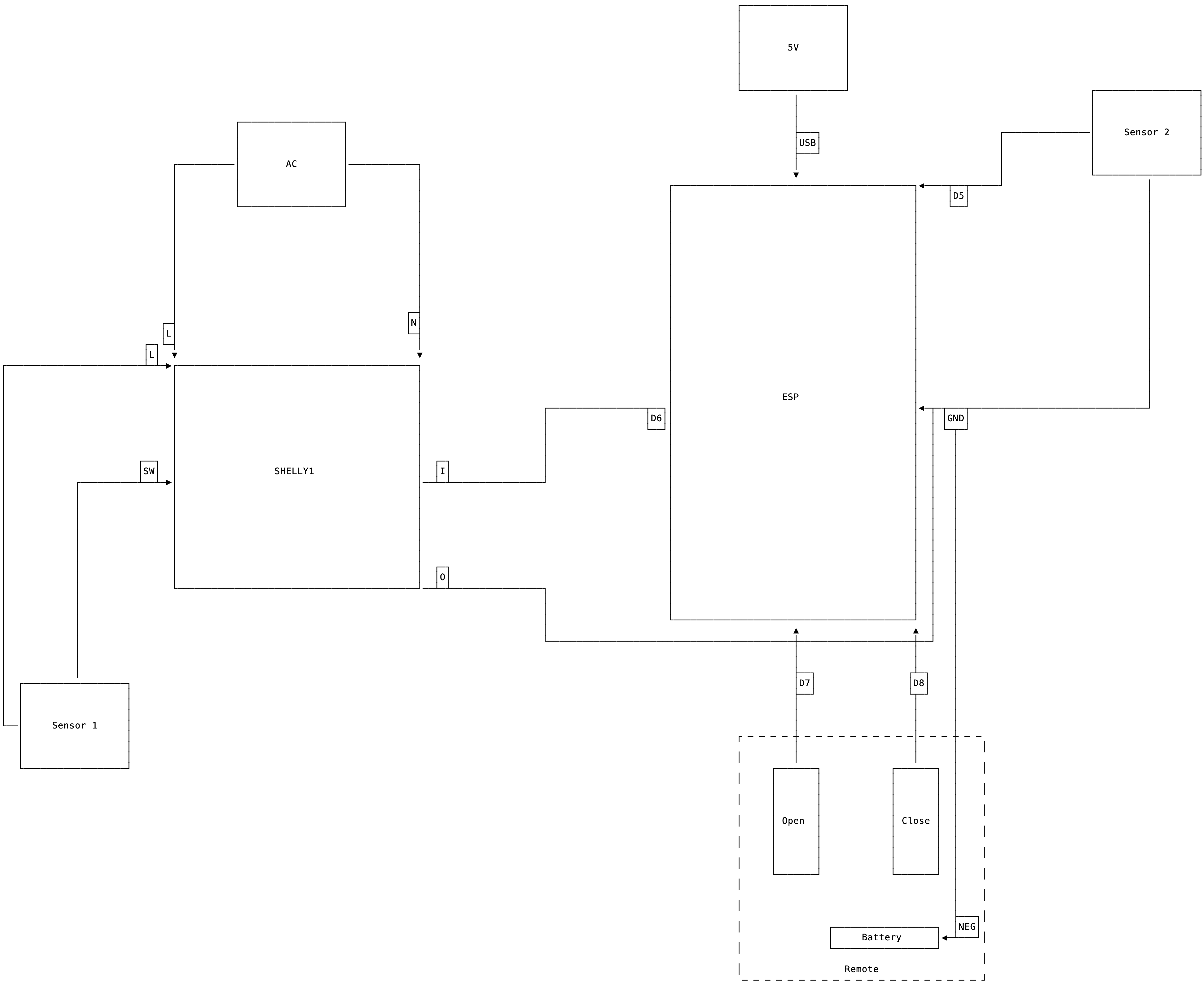
Circuit design
It doesn’t look too good, as I need two contact sensors and three power sources (AC, phone charger, battery), but it works flawlessly!
The firmware is not that complicated either:
#define closes 15    // D8
#define opens 13     // D7
#define activates 12 // D6
#define sensor 14    // D5

void setup() {
  pinMode(closes, OUTPUT);
  pinMode(opens, OUTPUT);
  pinMode(activates, INPUT_PULLUP);
  pinMode(sensor, INPUT_PULLUP);
  pinMode(LED_BUILTIN, OUTPUT);
  Serial.begin(115200);
}

void loop() {
  while (!digitalRead(activates)) {
    digitalWrite(LED_BUILTIN, HIGH);
    if (digitalRead(sensor)) {
      digitalWrite(closes, HIGH);
    } else {
      digitalWrite(opens, HIGH);
    }
    delay(100);
  }
  digitalWrite(closes, LOW);
  digitalWrite(opens, LOW);
  digitalWrite(LED_BUILTIN, LOW);
}
It keeps reading the activates input, which is the Shelly output.
When it closed, we keep reading the sensor and writing HIGH to either
opens or closes, depending on what the sensors tells us.
We give it a 100ms delay, and check again, so it more or less respects the pulse
time configured on the Shelly1.
Finally, in the end, we write LOW to opens, closes and the LED_BUILTIN.
You might be wondering why I didn’t do the whole thing in the ESP, since I’m already using it anyway. Well, the Shelly1, and some other models, have an alternative OSS firmware with native Homekit integration, and I didn’t want to lose that.
I’m also very noob in all this electrical engineering thing, and didn’t want to start with something too complex. Even for this simpler design, I had the help of friend that knows what he’s doing. Still, one of the Shelly1s I got is definitely dead - I’m not sure how, which worries me a little bit.
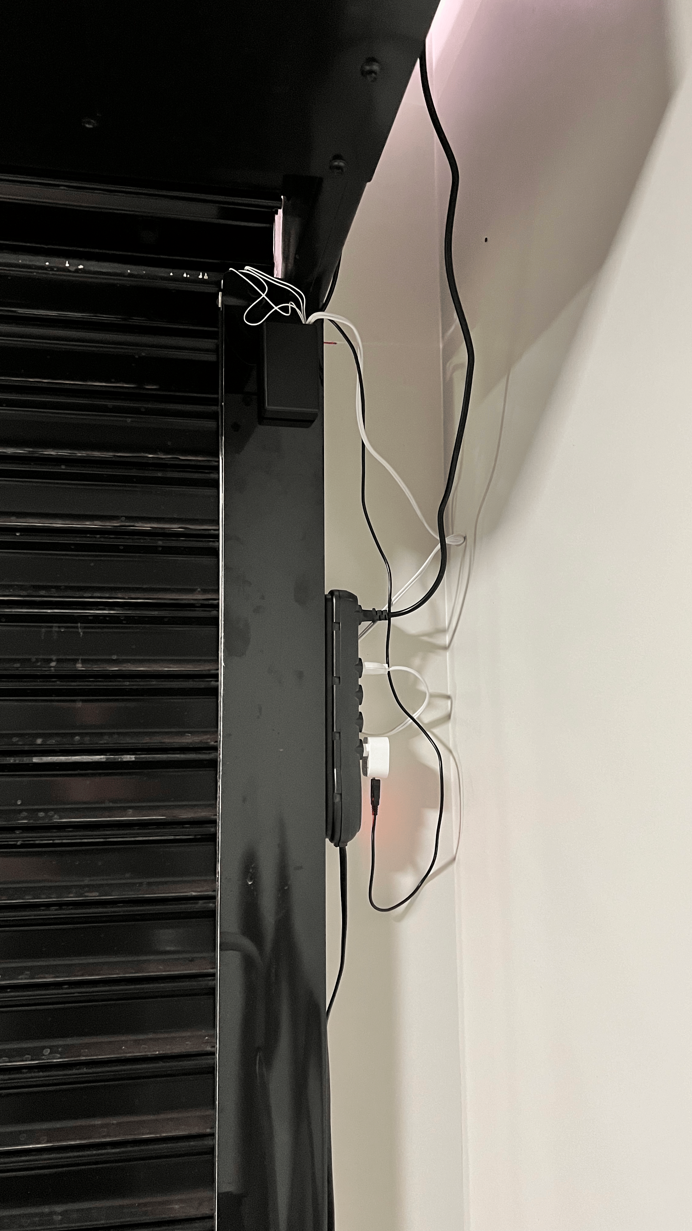
Here are some pictures:
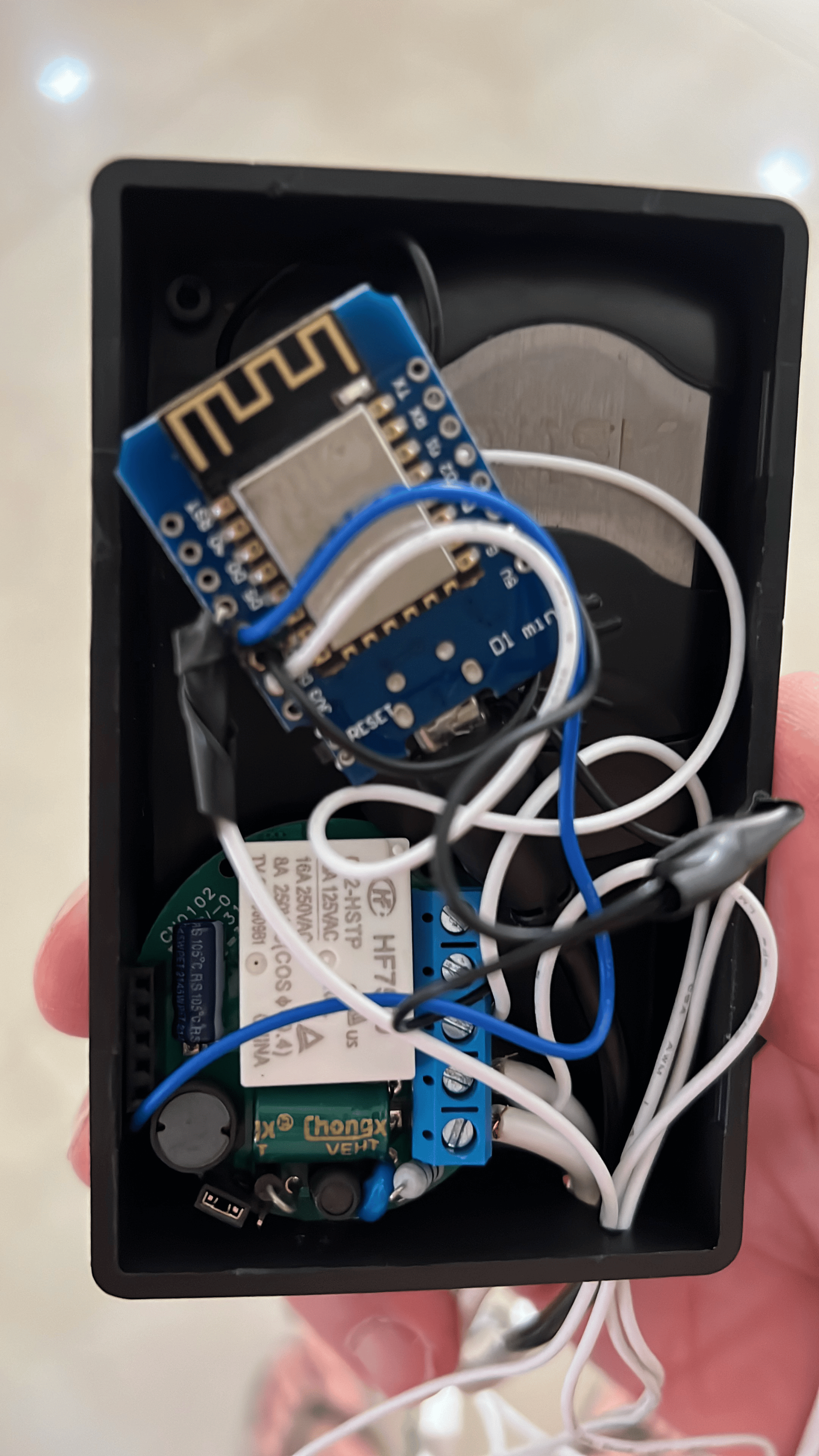
A box full of gambiarra.
It ain't pretty, but its honest work.
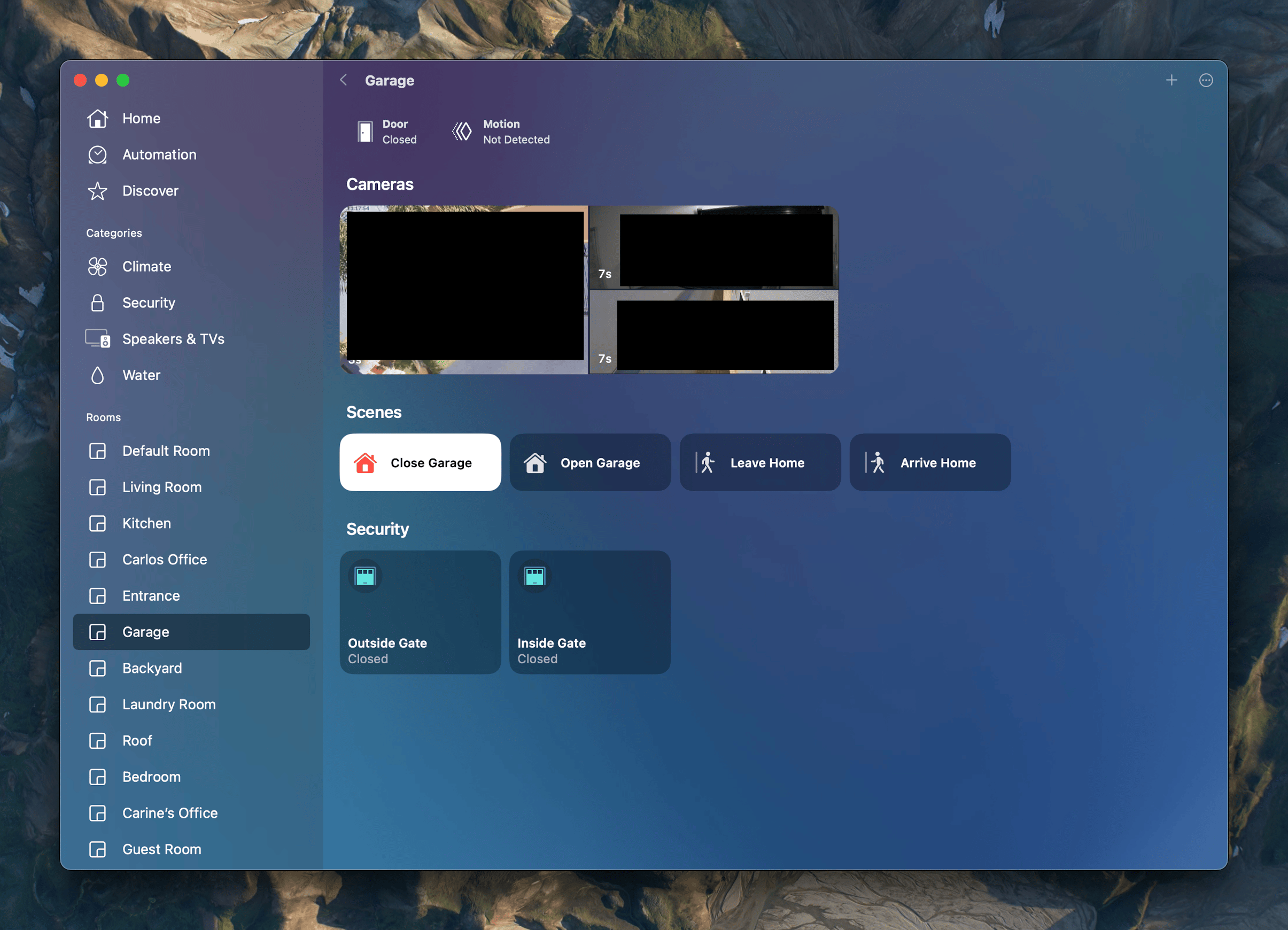
Garage room in Apple Home (cameras redacted).
Definitely need to organize the wires a bit better. It also wouldn’t hurt to either power the Shelly with DC too, or find a small enough transformer to fit inside the box (which is already very full).
Another option is to remove the Shelly entirely, and write the firmware for the ESP. We’ll see.
If you want to try it yourself, here’s the source code for the firmware I wrote.
Good luck!
—
Thanks for reading, see you in the next one!
and another one to stop, but that’s not really relevant. ↩︎